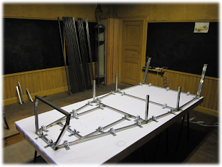
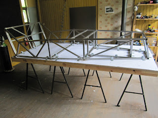
It is now time to place and tack the uprights (U3-U4-U5-U6) tubes, using a square and a spirit level.
Au moment du « pointage » (accroche des tubes entre eux par un point de soudure), il faut trouver des ruses pour supporter les tubes dans la bonne position. Ceux-là (SB1) ont un angle de 10°, et les équerres magnétiques ne suffisent pas.
When tacking the tubes together, I need to find some tricks to hold them in the right position. These ones (SB1) should have a 10° angle, and I can't use a magnetic bloc to do the job.
Le châssis prend de la hauteur...
The chassis is getting higher...
... et moi aussi ! Mais moi, je triche : je suis sur l'estrade !
... so do I, but I cheat : I'm on the stage !
Il faut maintenant fermer le « cube ». Les rails supérieurs avant droite et gauche TR1 et TR2 sont les plus longues pièces de l'ouvrage (1472mm).
Now it is time to close the "cube". Front top rails TR1 and TR2 are the longest tubes of the chassis (1472mm).
C'est aussi un bon moyen de s'assurer que tout est bien aux bonnes dimensions et bien à l'équerre. Bien sur quelques ajustements sont (déjà !) à faire pour que les rails viennent se positionner exactement où ils doivent.
It is also a good way to start checking that everything is at the right dimension and perfectly square. Of course, a few adjustments have (already !) to be done in order to get everything at the exact right place.
Here too, I have to find tricks. The lower edge of this top rail should match with the front edge of the upright. As it is 25mm section, 2mm wall thick, the inside section is 21mm. I put a piece of 20mm section tube and and piece of 3mm thick plate. This way, I get a perfectly flat surface and on exactly the same vertical plane as the edge of the upright, so I can place the top rail exactly where it should be. For tacking, I use a magnetic block on which the top rail is lying.
Je peux ainsi installer les tubes supérieurs du cockpit (TR3-TR4-TR8-TR9)
I can now install the cockpit top rails (TR3-TR4-TR8-TR9)
Après ça, les montant de fixation de triangle de suspension avant U1 et U2 (que je devrais repositionner plus tard avec le gabarit de suspension, voir mon post précédent concernant le cadre avant). Mon conseil est, comme pour le cadre avant, d'utiliser le gabarit de suspension directement pour positionner correctement ces tubes.
After that, the front suspension triangle uprights U1 and U2 (the ones I will have to remove and tack again later, using the suspension jig, see my previous thread about the front frame). My advice is, as for the front frame, to use directly the suspension jig to correctly place these tubes.
Ainsi que les éléments du cadre arrière du cockpit (SB3-SB4-SB5-SB6), sur lesquels viendront reposer les dossiers des sièges.
As well as the cockpit rear frame elements (SB3-SB4-SB5-SB6), where the seat backrests will rest (sorry for my poor English...)
La découpe de certains de ces tube (SB5 et SB6) n'est pas une partie de plaisir, et une précision à ce sujet est disponible sur le forum Haynes.
J'ai personnellement du m'y reprendre à plusieurs fois, et pour le coup, ma scie Rage n'a pas pu m'offrir la combinaison d'angles voulu sur l'une des extrémités. Pour m'en sortir, j'ai du démonter certaines pièces et prendre le tube par derrière (j'en vois qui rigolent !) pour obtenir ce que je voulais.
Cutting some of these tubes (SB5 and SB6) has been a real pain, but more details about that are available in the amendments section of Haynes forum
I had to do it a few time before getting the right angles, and I have to confess that I reached the limits of my Rage saw, which couldn't offer straightly the right combination of angle cuts for one of the ends. I had to remove some parts of the saw and take the tubes from the back (I can hear you laughing !) to get there.
Et puis les renforts diagonaux (D1-D2-D3-D4-D7-D8). Le "treillis" prend forme !
And the diagonal bracing tubes (D1-D2-D3-D4-D7-D8) : the "mesh" is taking shape !


Aucun commentaire:
Enregistrer un commentaire